| Bravo Illustrated Guide |
Sac-NYCF Fiber Optic Termination |
|
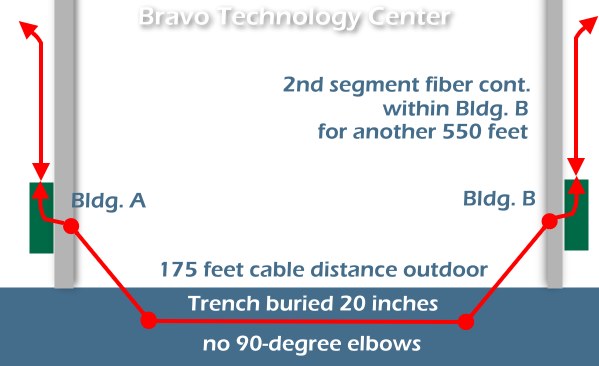
Project Summary: To implement a Fiber Optic Gigabit Ethernet backbone for IT infrastructure linking 2 buildings with total span of 800 feet. This includes a 175 feet outdoor underground trench, built with 3 layers complete with bedrock and drainage. Scope: This illustrated guide covers only the fiber termination portion of the project. The specifications for and discussions about options evaluation, network interconnection (including the indoor 550 ft segment of fiber optic) are furnished under separate documents. |
Bill of
Materials (italic = user furnished):
|
Copper-Fiber Transceivers, fiber optics cable, and Fiber SC connectors/couplers:
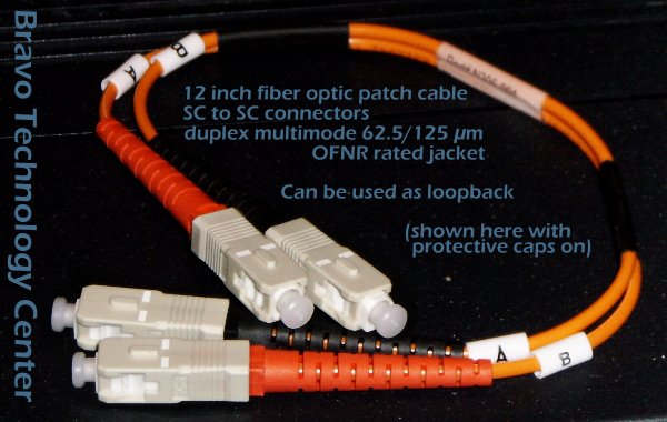
Short patch cable, to be stored inside main building termination housing
for emergency diagnostics. Notice that A goes to B and B goes to
A.'That's the correct way to interconnect Transmit to Receive and vice
versa.
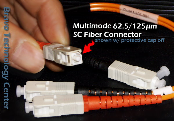
Protective cap removed.
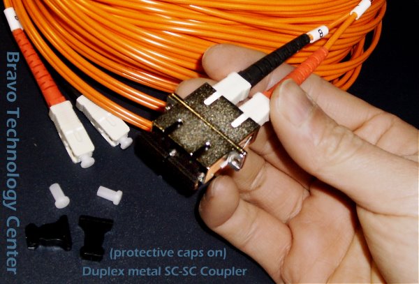
Heavy duty metal couplers with protective caps on 1 side, and duplex
cables plugged in to the other.
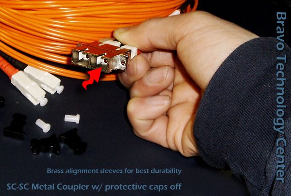
Protective caps off, revealing the brass alignment sleeves inside.
Ceramic sleeves provide the highest alignment precision but very poor
wear and durability. Brass sleeves provide sufficient precision for this
relatively short haul (800 feet total) using multimode. Plastic sleeves
should be avoided (not worth the savings).
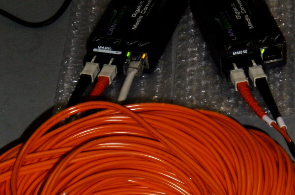
2x gigabit fiber-copper transceivers being testing on bench, simulating
long haul distance.
Fiber Termination Housing Fabrication:
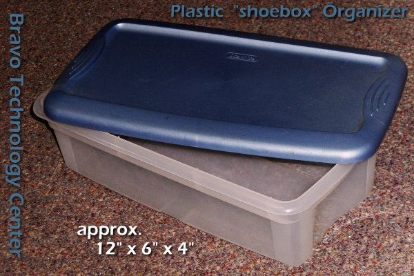
Box chosen as fiber termination housing at both point-of-entrances for
the cross-building trench.
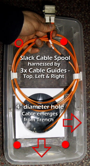
Interior layout of fiber termination housing.
- The 2 arrows point to suggested openings for phone and other cables.
- The box is shown in it actual vertical orientation as mounted on the wall.
- Fiber will exit the top of box via couplers, and naturally rise to ceiling for the indoor segment.
- Slack cable spool is harnessed by cable guides at top, left and right.
- Mount box to wall securely:
- Use of washers at the 4x mounting points is mandatory, as the box is made of soft materials
- Use plastic wall anchors or even toggle bolts as needed, to provide a solid mounting to the wall
- Box must be able to withstand pressure of cable plugging and general bumping
- If box is detached from wall unexpectedly, damage to trenched fiber cable could result from the tearing
- optional but recommended: cup holder hooks near the bottom of box, to anchor the 2x pull strings, to prevent accidentally losing them into the trench, the weight of string is naturally pulling.
- Loopback test cable can be store inside this box.
- Tape IT emergency contacts+ management notification info on side of lid
- After servicing, always re-place the snap-on lid to cap the trench pipe, and protect the fragile content
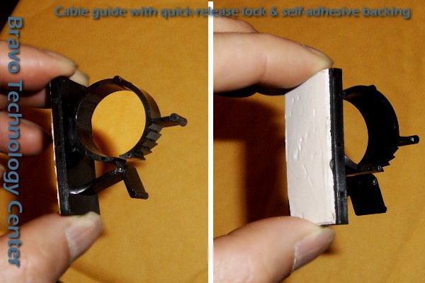
Close-up view of self locking computer cable guide w/ quick-release tab
and self-adhesive backing. Since termination housing is located in human
hospitable environment, extreme temperature variation is not expected.
There is no need to supplement with bolt mounting.
 If
specialized cable guides are not available, common household cup holders
can be used.
If
specialized cable guides are not available, common household cup holders
can be used.
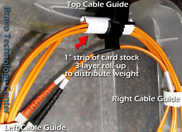
Pay particular attention to the top cable guide, as that's where the
bulk of load is asserted. The lack of special curved resting surface (as
provided by expensive metal housing) is easily solved by an 1-inch strip of
card stock paper rolled up to distribute weight and eliminate pinching.
This is critical if the slack spool is large and heavy. Pinching
prevents normal refraction as expected and creates signal leakage,
possibly rendering the cable non-functional. Severe long-term pinching could
eventually damage the jacket (even core and cladding) physically.
Special care for fiber optic installation:
- uncoil/recoil carefully to avoid kinks
- loosely fitted paper roll and absolutely no tightening of cable harnesses, they're guides -- not clamps!
- never use vinyl cable ties to tightly bundle!
- utilize the entire space to avoid tight turning radius
- for the trenched segment, we have calculated and tripled measured to arrive at a closely-matched cable distance of 175 ft and pre-fabricated cable length of 200 ft, resulting in a very manageable 12 ft slack at each end.
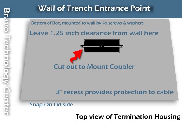
 It's important to leave 1.25" of clearance between the coupler and the
wall, to accommodate large adult hands with jersey gloves. This allows
unobstructed plugging and unplugging of cables without risk of wrist
injuries or cable damages. The couplers must be sufficiently recessed
from the front, so that the protrusion of the box provides protection
from accidental bumping of cables.
It's important to leave 1.25" of clearance between the coupler and the
wall, to accommodate large adult hands with jersey gloves. This allows
unobstructed plugging and unplugging of cables without risk of wrist
injuries or cable damages. The couplers must be sufficiently recessed
from the front, so that the protrusion of the box provides protection
from accidental bumping of cables.
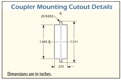
Cutouts (follow this sequence):
- small retangular hole for coupler. Precision is important. Do not subject the coupler to any squeezing or bending at any point.
- medium round access hole(s) for your telco trunk cable, plus dummy coax for structural strain-bearing during pull, and additional spare copper CAT-5e runs for future use. Provide grommets.
- large hole for trench pipe entrance. Rough cut is fine. Once this is done, a significant portion of cross-bracing strength is lost. Avoid any needless further handling and undue warpage pressure to the box.
Overall Cable Segments Schematic Diagram:
Bonne chance, Ernesto ! This is a great project for your niche. It's high-end and technical—an impressive addition to your repertoire, while taking full advantage of your managerial, logistical and mechanical know-hows.
-SCC
BRAVOTECH * MEMOS * INFO * TECH DEPOT * OPEN LETTER * EYEFUL TOWER